✨ Overview
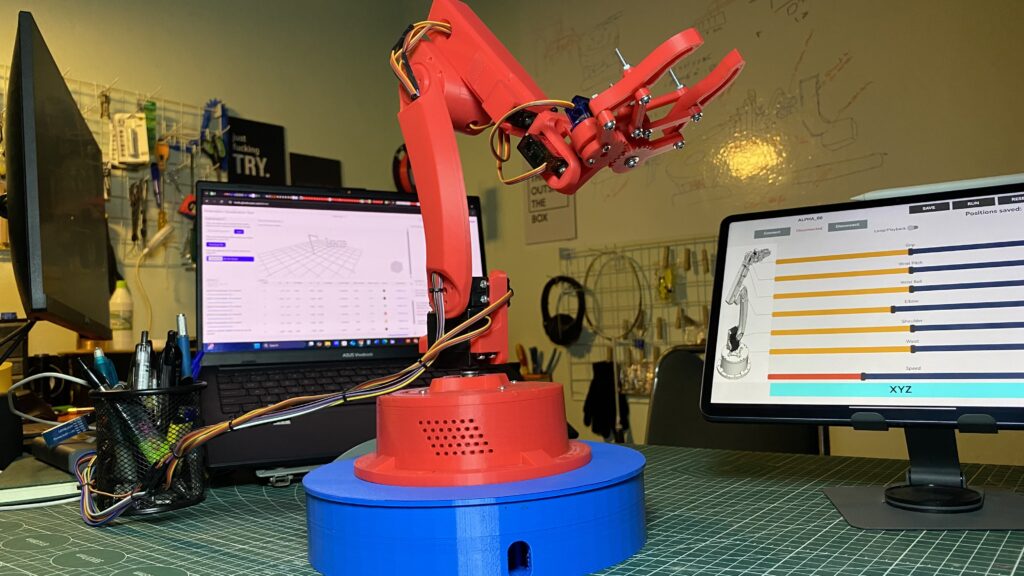
This project showcases a 6 Degrees of Freedom (DOF) Robot Manipulator (5+1), a complex and fully functional robotic arm designed and fabricated using advanced prototyping techniques. The manipulator is controlled via an Android application through Bluetooth, and its precision is ensured using Forward Kinematics (FK) calculations. The project demonstrates expertise in mechanical design, electronics, programming, and control systems.
✨ Project Objectives
• Design a fully functional 6 DOF robotic manipulator with accurate movement and precision.
• Implement Forward Kinematics (FK) using the Denavit-Hartenberg (DH) method for precise end-effector positioning.
• Develop an Android application for user-friendly robot control via Bluetooth.
• Showcase comprehensive skills in CAD design, 3D printing, Arduino programming, and app development.
✨ project components
1. Mechanical Design and Fabrication
• CAD Software: SolidWorks.
– Designed the entire manipulator structure with precise joint configurations.
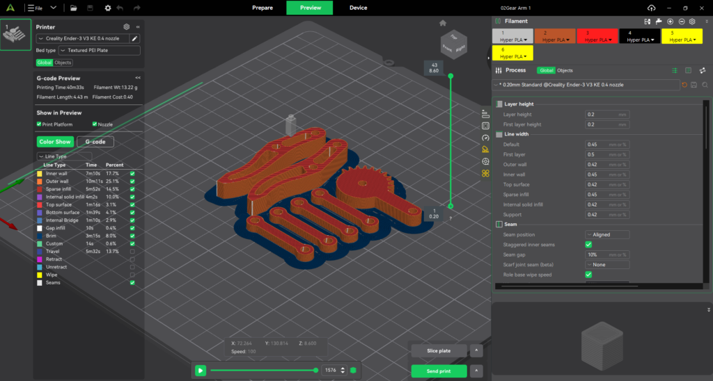
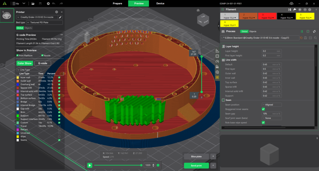
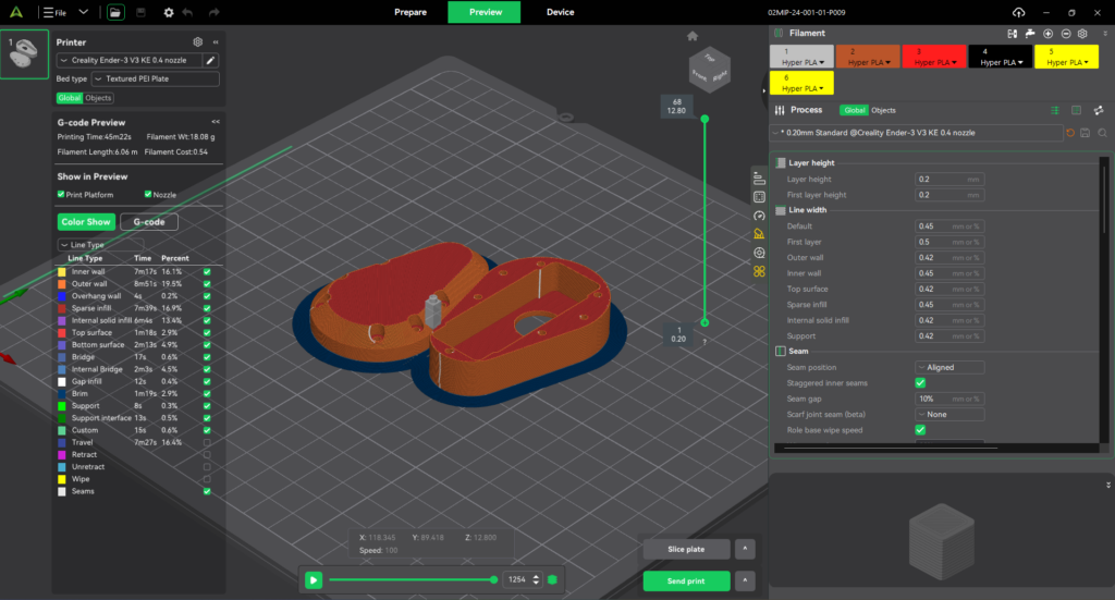
– Optimized for 3D printing using FDM technology.
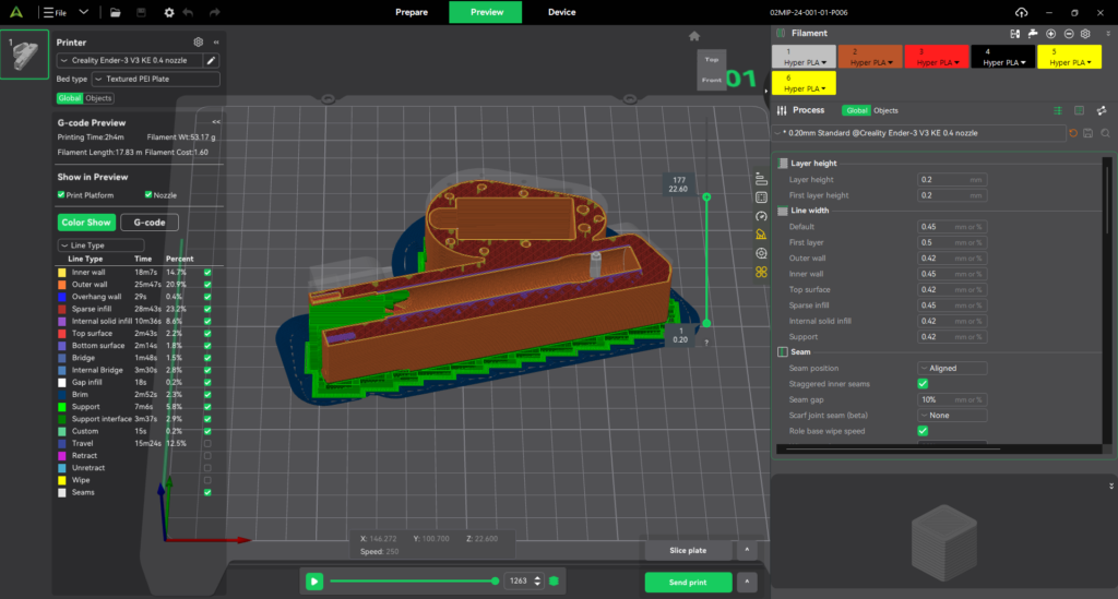
• 3D Printing: Ender 3V3KE (Creality Print 6.1)
– Material: PLA/+ (Polylactic Acid) for lightweight and durable parts.
– Assembly: Parts were printed, cleaned, and assembled for a smooth range of motion.
• Motors:
– MG996R (High torque) for main joints.
– SG90 (Lightweight) for smaller, precise movements.
2. Electronics and Control System
• Microcontroller: Arduino Uno R3.
• Servo Motor Driver: PCA9685 PWM Servo Driver for simultaneous multi-servo control.
• Communication: Bluetooth Module (HC-05) for wireless control.
• Power Supply: Dedicated 5V for servo stability.
3. Software Development
• Arduino Programming (C++):
– Control logic for 6 servo motors using PCA9685.
– Implementation of Forward Kinematics using DH parameters.
– Bluetooth communication setup for real-time control.
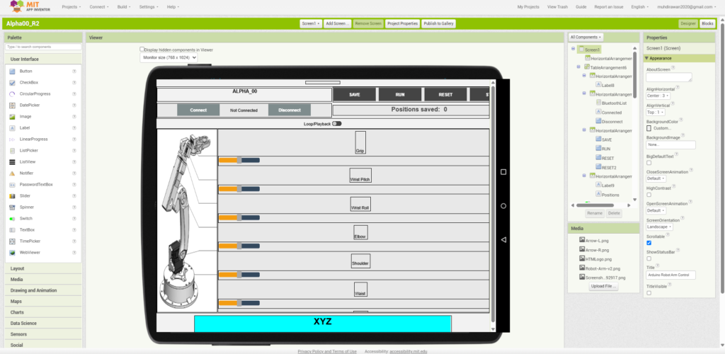
• Android Application (MIT App Inventor):
– User-friendly interface for controlling each joint via Bluetooth.
– Live display of XYZ coordinates of the end-effector.
✨ Mathematical Model (Forward Kinematics)
Denavit-Hartenberg (DH) Parameters
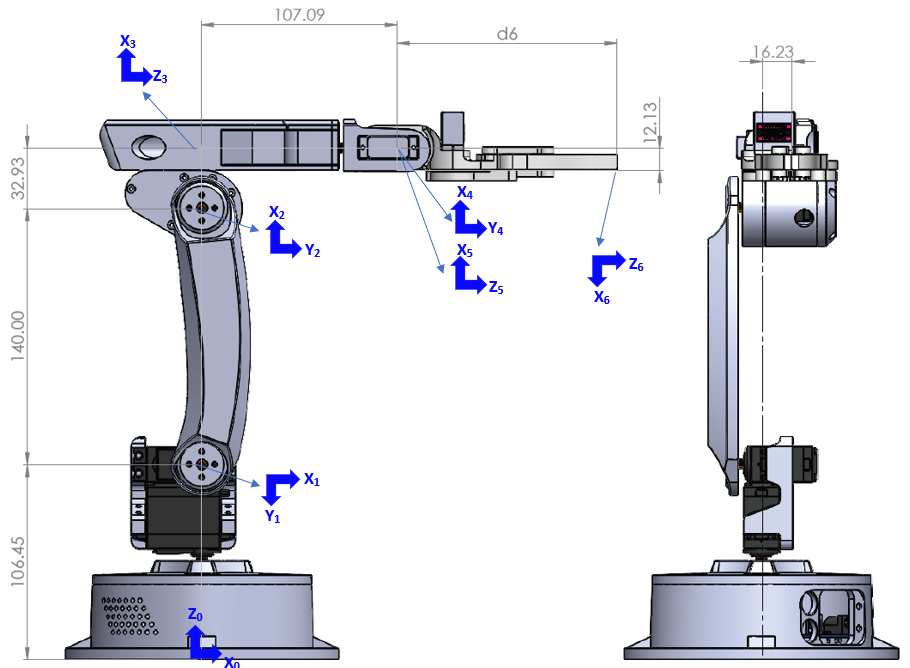
| Joint | θi (rad) | θi offset (rad) | di (mm) | ai (mm) | αi (rad) |
|---|---|---|---|---|---|
| 1 | θ1 | 0 | 106.45 | 0 | -π/2 |
| 2 | θ2 | -π/2 | 0 | 140 | 0 |
| 3 | θ3 | -π/2 | 16.23 | 32.93 | -π/2 |
| 4 | θ4 | π/2 | 107.09 | 0 | π/2 |
| 5 | θ5 | -π/2 | 0 | 0 | -π/2 |
| 6 | 0 | 0 | d6 | 12.13 | -π/2 |
Forward Kinematics Calculation
The Forward Kinematics is calculated using the Denavit-Hartenberg transformation matrix:
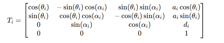
• These matrices are multiplied in sequence to calculate the final end-effector position [x,y,z].
• The calculated end-effector coordinates are sent to the Android app for real-time display.
✨ Coding Example (Arduino – Forward Kinematics)
void computeAndSendFK() {
float theta[6];
See more
void computeAndSendFK() {
float theta[6];
// Convert PWM to angle in radians with correct offsets
theta[0] = (map(currentServoPositions[0], 150, 600, 0, 180) * (PI / 180.0)) + 0; // θ1 offset = 0
theta[1] = (map(currentServoPositions[1], 150, 600, 180, 0) * (PI / 180.0)) – (PI); // θ2 offset = -π/2
theta[2] = (map(currentServoPositions[2], 150, 600, 0, 180) * (PI / 180.0)) – (PI/2); // θ3 offset = -π/2
theta[3] = (map(currentServoPositions[3], 150, 600, 180, 0) * (PI / 180.0)) + (PI/2); // θ4 offset = π/2
theta[4] = (map(currentServoPositions[4], 150, 600, 0, 180) * (PI / 180.0)) – (PI/2); // θ5 offset = -π/2
theta[5] = 0; // Joint 6 is assumed fixed for RnD (ongoing develop for Prismatic).
// DH parameters according to the table
float a[] = {0, 140, 32.93, 0, 0, 12.13}; // ai (mm)
float d[] = {106.45, 0, 16.23, 107.09, 0, 120}; // di (mm) – d6 should be set to assummed value
float alpha[] = {-PI/2, 0, -PI/2, PI/2, -PI/2, -PI/2}; // αi (rad)
// Initial homogeneous transformation matrix
float T[4][4] = {
{1, 0, 0, 0},
{0, 1, 0, 0},
{0, 0, 1, 0},
{0, 0, 0, 1}
};
// Calculate transformation matrix for each joint
for (int i = 0; i < 6; i++) {
float ct = cos(theta[i]), st = sin(theta[i]);
float ca = cos(alpha[i]), sa = sin(alpha[i]);
float T_i[4][4] = {
{ct, -st*ca, st*sa, a[i]*ct},
{st, ct*ca, -ct*sa, a[i]*st},
{0, sa, ca, d[i]},
{0, 0, 0, 1}
};
// Matrix multiplication T = T * T_i
float result[4][4];
for (int r = 0; r < 4; r++) {
for (int c = 0; c < 4; c++) {
result[r][c] = 0;
for (int k = 0; k < 4; k++) {
result[r][c] += T[r][k] * T_i[k][c];
}
}
}
// Update T with multiplication result
for (int r = 0; r < 4; r++) {
for (int c = 0; c < 4; c++) {
T[r][c] = result[r][c];
}
}
}
// End-effector position
float x = T[0][3];
float y = T[1][3];
float z = T[2][3];
✨ Skills demonstrated
• Mechanical Design: SolidWorks (3D Modeling, Assembly).
• 3D Printing: FDM Technology, Prototyping, Assembly.
• Microcontroller Programming: Arduino (C++), PCA9685 Control.
• Mathematical Modeling: Forward Kinematics using DH Method.
• App Development: Android App (MIT App Inventor) for Bluetooth Control.
• Electronics: Servo Motor Control, Bluetooth Communication, Power Management.
✨ Project gallery
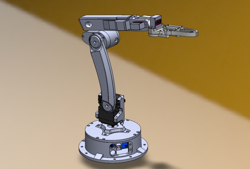
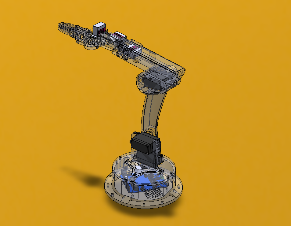
CAD Design and 3D Model (SolidWorks).
3D Printing Process and Assembly.
Code & Electronics Setup – Schematic Diagram (Arduino, PCA9685, Servo Motors, & HC-05).

Android Application Interface (Control Interface).
App User Interface (MIT App Inventor)
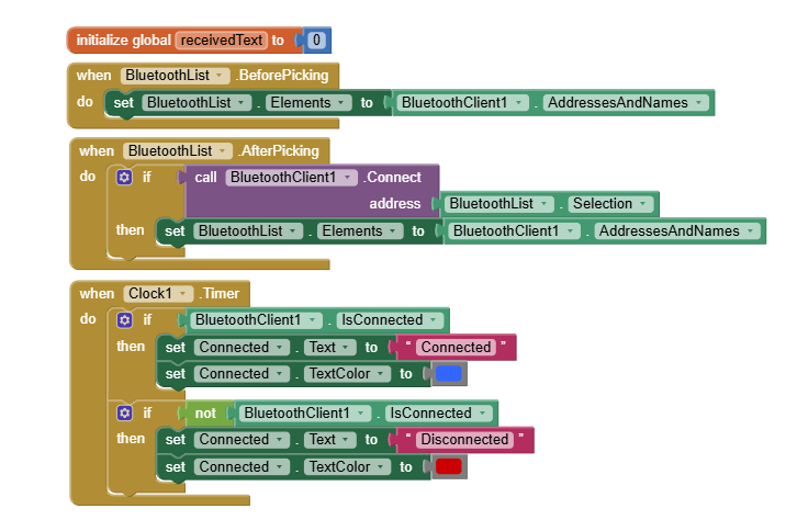
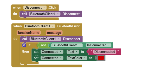
Block – Bluetooth Connect & Disconnect
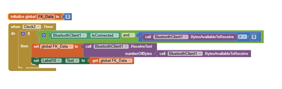
Block – Receiving Forward Kinematic (XYZ) data from Arduino by Bluetooth
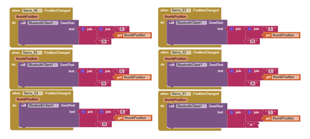
Block Slider – Sending data to Arduino for Servo PWM Control
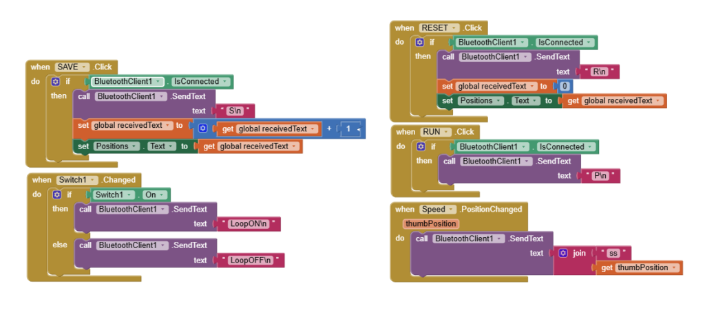
Block Button – RUN, RESET, Speed, Save, Loop
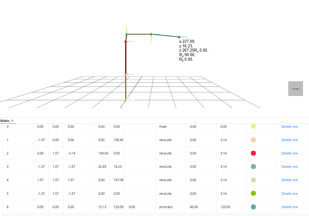
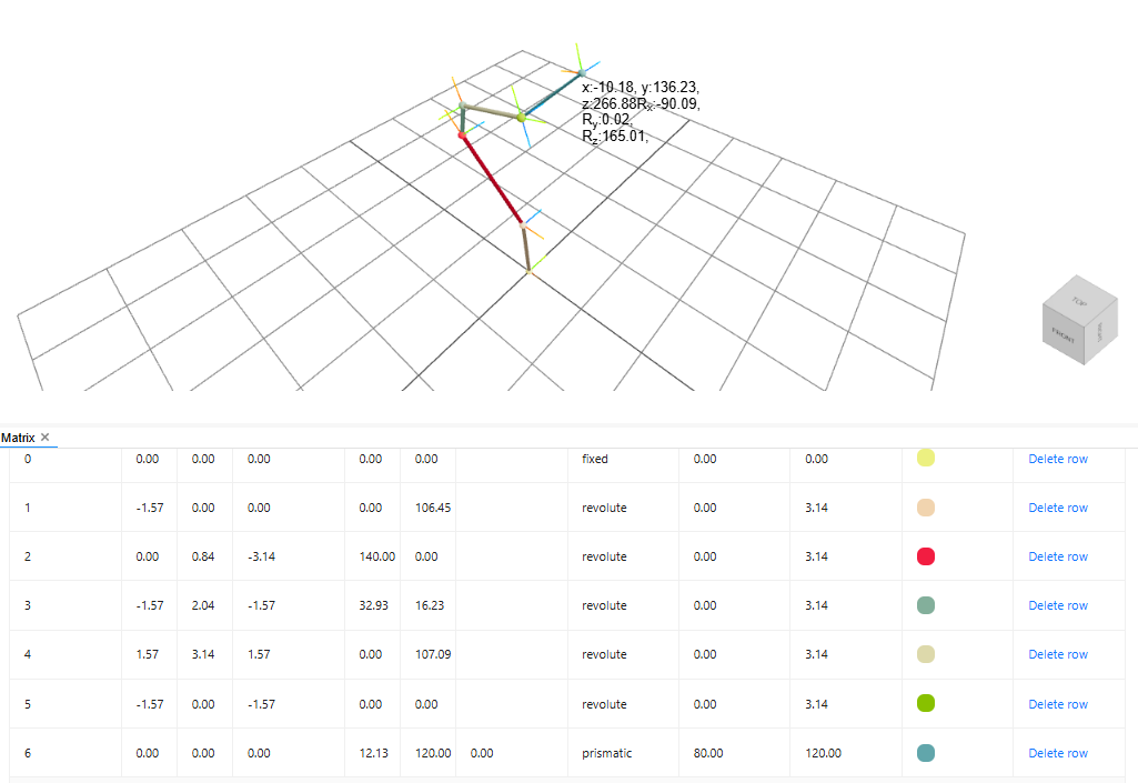
Testing Forward Kinematics Calculation.
Simulating on glowbuzzer